
Description
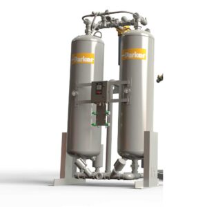
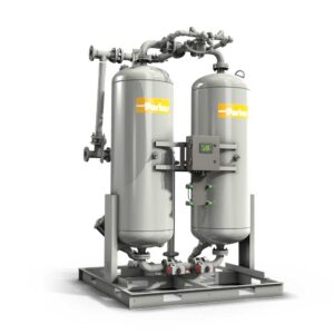
Deltech’s DSHD Series Modular Desiccant Air Dryers protect moisture sensitive applications requiring low pressure dew points. Delivers dew points of ISO 8573-1: 2010 Class 1 (-94°F, -70°C) and Class 2 (-40°F, -40°C) with flow rates of 7 to 40 scfm (12 to 68 nm3/h). Critical applications include labs, hospitals, pharmaceutical manufacturing and other high-tech installations.
The DSHD Series incorporate a time proven design, with superior features and reliability, in a compact and easy to install package.
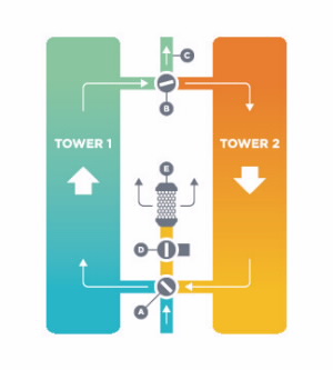
Compressed air enters the dryer and is directed to Tower 1 by valve (A), and then to the dryer outlet through shuttle valve (B). A portion of the dried air is throttled to near atmospheric pressure by means of orifice (C). This extremely dry, low-pressure air flows through and regenerates the desiccant in Tower 2 and is exhausted through purge/repressurization valve (D) and exhaust muffler (E) to atmosphere. After a set time, the automatic solid state timer closes purge/repressurization valve (D) allowing Tower 2 to repressurize slowly. At the end of 2 minutes, valve (A) shifts and purge/ repressurization valve (D) reopens. The main air flow is now dried by Tower 2 while Tower 1 is being regenerated.
| Model | INLET FLOW RATING1 SCFM (NM3/H) |
PURGE FLOW2 SCFM (NM³/H) |
IN/OUT CONNECTIONS |
||||||
|---|---|---|---|---|---|---|---|---|---|
| -40°F | (-40°C) | -94°F | (-70°C) | Average | Maximum | IN | |||
| DSHD-7 | 7 | 12 | 5 | 8 | 1.5 | 2.3 | 1.8 | 2.7 | 1/2″ NPT |
| DSHD-13 | 13 | 22 | 9 | 15 | 2.7 | 4.5 | 3.7 | 5.1 | 1/2″ NPT |
| DSHD-18 | 18 | 31 | 12 | 20 | 3.7 | 5.7 | 4.4 | 6.5 | 1/2″ NPT |
| DSHD-21 | 21 | 36 | 14 | 23.5 | 4.6 | 7.2 | 5.4 | 8.1 | 1/2″ NPT |
| DSHD-27 | 27 | 46 | 18 | 30.5 | 5.3 | 8.3 | 6.2 | 9.2 | 1/2″ NPT |
| DSHD-40 | 40 | 68 | 27 | 45.5 | 9.7 | 15 | 11.6 | 16.1 | 1/2″ NPT |
1 Inlet flows are established in accordance with CAGI (Compressed Air and Gas Institute) standard ADF-200, Dual Stage Regenerative Desiccant Compressed Air Dryers – Methods for Testing and Rating. Conditions for rating dryers are: inlet pressure – 100 psig (7 kg/cm2); inlet temperature – saturated at 100°F (38°C).
2 Average Purge Flow is the total amount of air used to purge and repressurize off-stream towers averaged over the cycle time. Maximum Purge Flow is the flow rate through the off-stream tower during that portion of the cycle the purge/ repressurization valve is open.
TABLE 2 – INLET & PURGE FLOW CORRECTION FACTORS
| INLET PRESSURE |
psig | 50 | 70 | 90 | 100 | 110 | 120 | 130 | 150 |
|---|---|---|---|---|---|---|---|---|---|
| kg/cm2 | 3.5 | 4.9 | 6.3 | 7 | 7.7 | 8.4 | 9.1 | 10.5 | |
| MULTIPLIER A | 0.31 | 0.54 | 0.83 | 1.00 | 1.09 | 1.17 | 1.26 | 1.44 | |
| MULTIPLIER B | 0.55 | 0.73 | 0.91 | 1.00 | 1.09 | 1.17 | 1.26 | 1.44 | |
CAPACITY CORRECTION FACTORS
- To determine maximum inlet flow at inlet pressures other than 100 psig (7 kg/cm2), multiply inlet flow from Table 1 by multiplier A from Table 2 that corresponds to system pressure at inlet of dryer.
- To determine purge flow at inlet pressures other than 100 psig (7 kg/cm2), multiply purge flow at 100 psig (7 kg/cm2), from Table 1 by multiplier B from Table 2 that corresponds to system pressure at inlet of dryer.
- To determine outlet flow capacity, subtract purge flow from inlet flow.